From the process of electrical engineering, it can be known that in a series resonant circuit containing inductance L, capacitance C, and active resistance R, voltage resonance occurs when the reactance is equal (X L=X C). When the frequency is e, resonance in the series circuit can be obtained. D is consistent with the frequency of free oscillation in the circuit.
Normally, the current in a circuit is determined by rotation

Resonance (XL=XC)

Therefore, in resonance, when ƒ=ƒ 0, a series circuit has a minimum resistance equal to the circuit and an active resistance of e.
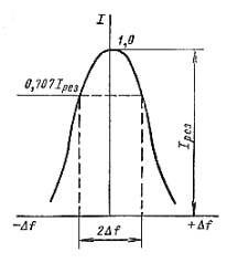
The quality factor of a series resonant circuit indicates how many times the voltage on its components increases during resonance compared to the e applied to the circuit. The frequency dependence of current in a series circuit is called the resonance curve of the circuit.

The analytical expression for the road resonance curve is

I am the current in the circuit; ƒ is the frequency of the applied e. ƒ 0=Δ ƒ - The detuning of the circuit relative to frequency E. D I res=E/R current in the circuit at resonance.
According to the formula, we can conclude that the lower the Q coefficient of the circuit, the higher the resonance frequency, and the wider the resonance curve. In fact, the input signal of a circuit usually has a complex frequency composition. The circuit should skip the entire spectrum or frequency band while maintaining the necessary relationships between the various components of the complex signal. The bandwidth of the P-loop is called the frequency region, which is enclosed between the ordinate of the resonance curve and is equal to 0.707 I res (I res/√ 2).
The equation of the resonance curve indicates a clear equality

If necessary, determine the bandwidth corresponding to any other vertical axis using the formula

Where A is numerically equal to the number of I/I res that determine the passband.
The oscillation circuit has two opposite requirements: on the one hand, if possible, it should pass through the frequency spectrum (band) uniformly, and on the other hand, eliminate the possibility of external signals that do not belong to the useful input signal, but are slightly different from those frequencies and their extreme frequencies. Meanwhile, an ideal circuit with a rectangular resonance curve can best meet these requirements.


