The following figure shows a typical series resonance (also known as variable frequency resonance) circuit.
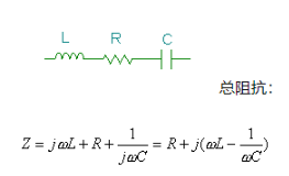
In many cases, R represents the loss resistance of an inductor, and in the case of a hollow coil, it simply represents the resistance of the winding. The resistance related to capacitors can usually be ignored.
The impedance of capacitors and inductors is fictitious and has opposite signs. Typically, for w0 L=1/w0C, the total imaginary part is 0, so the total impedance is R and w is 0 times. This frequency is the series resonant frequency.
The general impedance characteristics of this circuit are shown in the following figure.
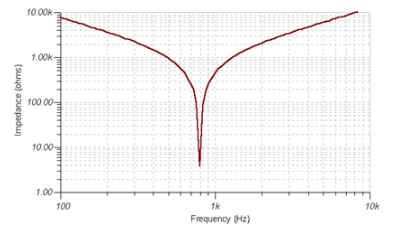
When w0 L=1/w0, each frequency of series resonance: or frequency in Hz: F0
This is the so-called Thompson formula.
If R is smaller than X, then the reactance near the resonance frequency of L and X C is the series resonance frequency, and we say that the circuit has good selectivity.
The selectivity of the quality factor Q is equal to the angular frequency We of each resonant frequency in the formula, and there is a more general definition of the quality factor:

Moreover, the voltage across voltage inductors or capacitors may be higher. At the resonant frequency of the entire voltage circuit, the total impedance of the circuit is Z=R.
Assuming the current passing through the circuit is I, the total voltage of the circuit is V=I * R. However, the voltage of inductors and capacitors

Therefore

At this point, the voltage of the inductor and capacitor is greater than the total voltage of the Q0 resonant circuit at the resonant frequency.
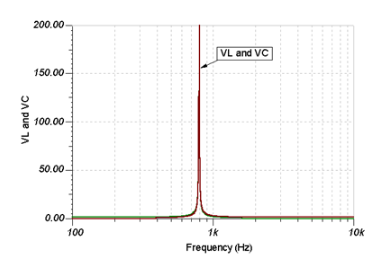
The following figure shows typical V operation L and VC voltages.
