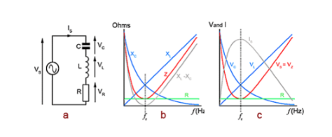
When the reactants are equal, series resonance occurs. The inductance reactance (XL) of frequency and inductance is:

The capacitance reactance (XC) is composed of:

The reactance frequency is directly proportional, and its graph is plotted as a straight line with the frequency (ƒ). The capacitive reactance is inversely proportional to frequency, as shown in the graph where ƒ is the curve. These two quantities indicate that, R, By planning together for the ƒ plot, it can be seen that the intersection of XC and XL is equal, so the graph of (XL-XC) must be on the frequency axis, which is zero.

The characteristics of series resonance in LCR circuits.
The LCR series circuit is designed to respond to the situation where the resistance (R) and impedance (Z) occur when the frequency of the power source (VS) changes from 0Hz to XC. Firstly, the circuit behaves as a capacitor, and the total impedance (Z) of the circuit falls on a very similar curve to XL-XC.
The relationship between individual component voltage and circuit impedance (Z) and power supply current (IS) (which is common to all series resonant device components). At a specific frequency ƒ r, it can be seen that XL-XC has dropped to zero, with only the circuit resistance R at the other end of the power supply. Therefore, the current flowing through the circuit at this time is the maximum value of a. Now VC and VL have equal values and opposite phases, so they will completely cancel out the others. The effective reactance is zero, and the circuit is completely resistive. When Z equals r, the circuit current (IS) will be at its maximum and will be in phase with the power supply voltage (VS) at its minimum value.
As the frequency increases beyond this resonance frequency (ƒ r), the impedance increases, and as XL is now the larger of the two reactions, the impedance curve begins to follow a linear graph closer to the value XL.
Below the resonant frequency, the circuit behaves as a capacitor, and below the resonant frequency, the circuit behaves as a resistor. The behavior of the ƒ r circuit becomes more and more like an inductor, and the XL-XC graph quickly becomes almost a straight line. The characteristic of LCR series circuits allows for this state.


