Product introduction
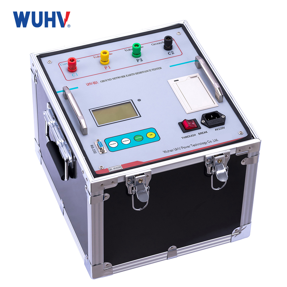
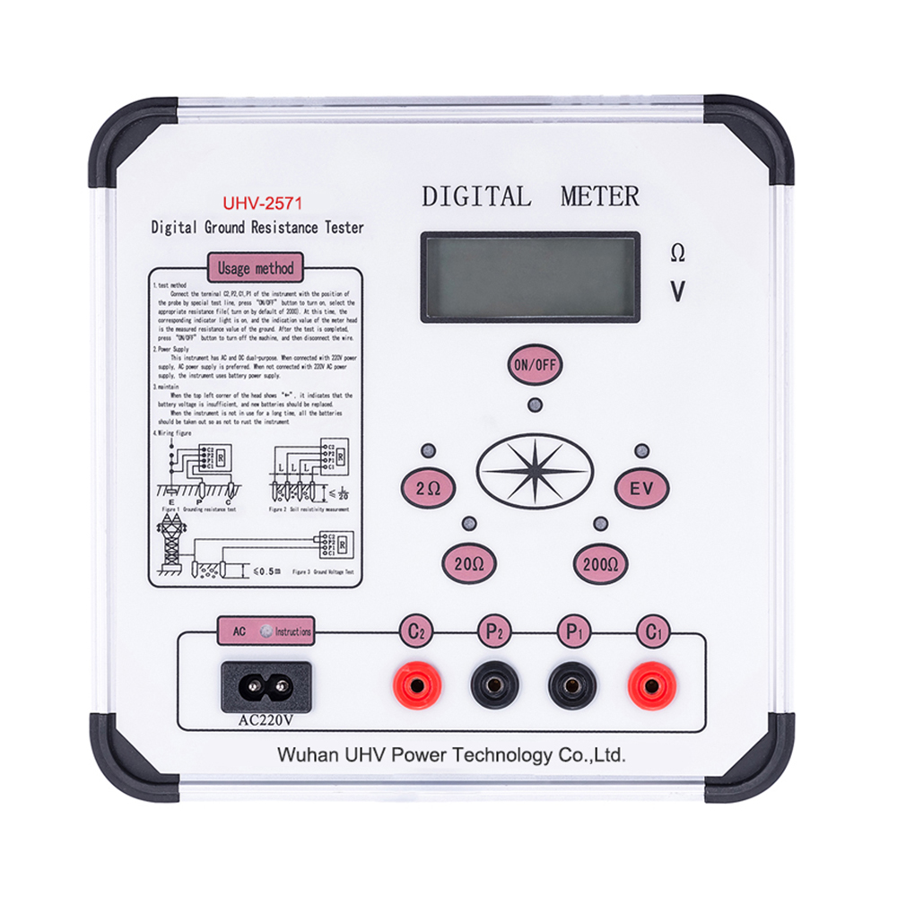
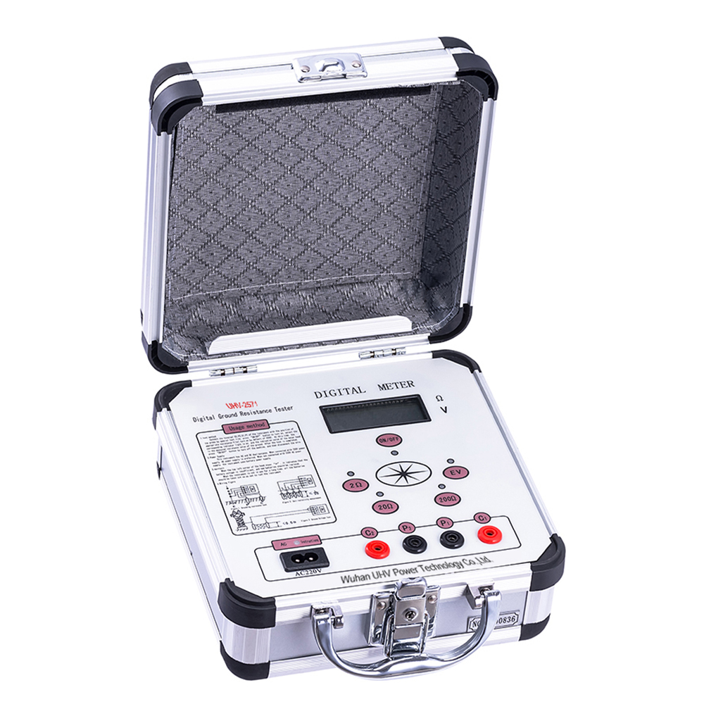
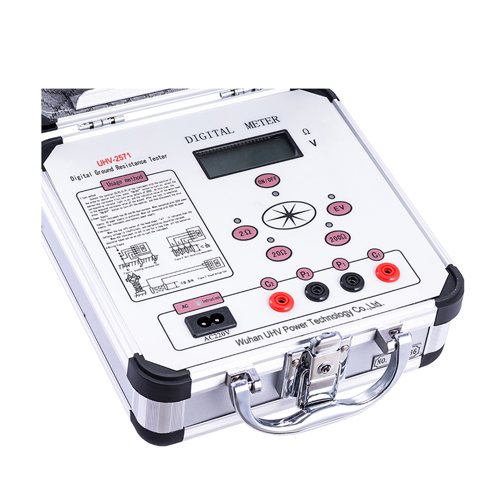
The ground resistance measuring instrument is a new type of ground resistance measuring instrument, which combines the three-end button and four-end button measuring methods by using advanced medium and large scale integrated circuit instead of the traditional manual manual power generation.
The working principle is that the DC/AC converter in the machine changes DC into low-frequency constant current of AC, and the circuit is formed by auxiliary ground electrode C and measured object E, which generates AC voltage drop on the measured object, and is fed into AC amplifier for amplification through auxiliary ground electrode P, and then sent to the meter head for display through detection. With the aid of multiplying power switch, three different quantity limit can be obtained: 0 ~ 2 Ω, 0 ~ 20 Ω, 0 ~ 200 Ω.
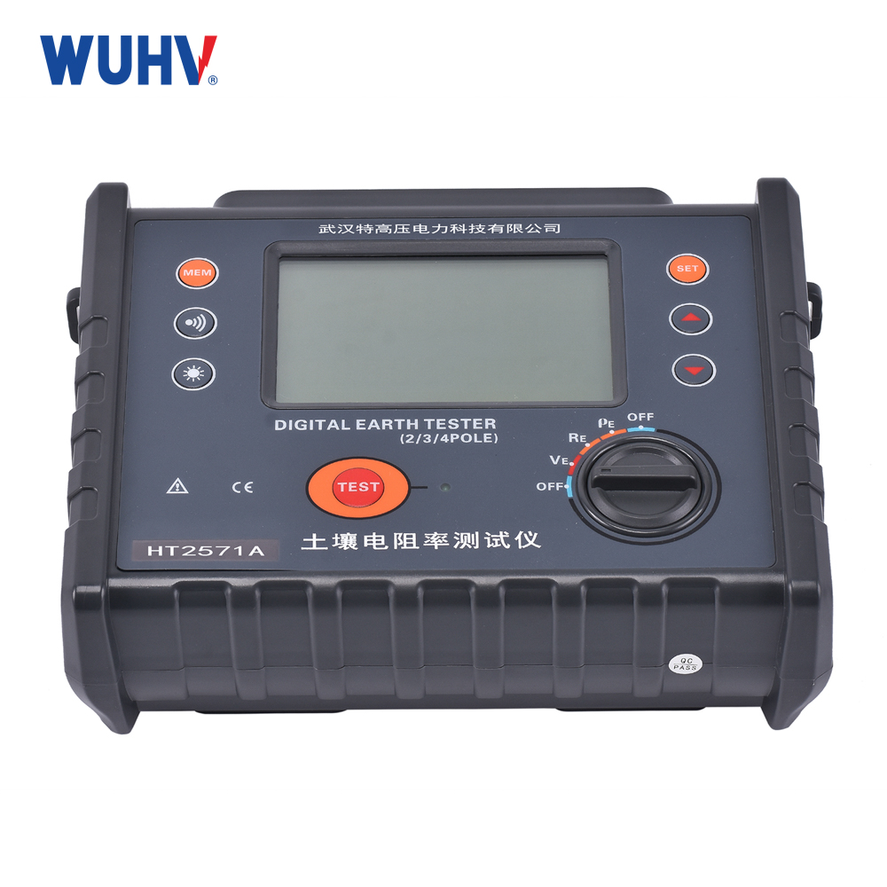
The earth resistance measuring instrument is suitable for measuring the earth resistance of various devices and the conductor resistance value of low resistance in electric power, post and telecommunication, railway, communication, mining and other departments. The table also measures soil resistivity and ground voltage.
 |  |  |
Production functions
Ground resistance measurement — Measures the ground resistance of grounding systems and grounding electrodes. Core measurement function with a range of 0 to 200Ω.
Low resistance measurement — Measures the resistance of low-resistance conductors.
Soil resistivity measurement — Used for measuring soil resistivity, applicable to grounding system design and grounding performance evaluation.
AC voltage measurement — Measures on-site AC / power frequency voltage with a range of 0 to 19.99V, assisting in evaluating power frequency interference at the grounding test site.
Technical parameters
| Conditions | The environment temperature | 0℃~+45℃ |
| Relative humidit | ≤85%RH | |
| Measuring range and constant current (RMS)) | Resistance | 0~2Ω(10mA),2~20Ω(10mA),20~200Ω(1mA) |
| Voltage | AC0~19.99V | |
| Measurement accuracy and resolution | Precision | 0~0.2Ω≤±3%±1d |
| 0.2Ω~199.9Ω≤±1.5%±1d | ||
| 1~19.99V≤±3%±1d | ||
| Resolution | 0.001Ω、0.01Ω、0.1Ω、0.01V | |
Measurement error caused by auxiliary grounding resistance and ground voltage | Allow auxiliary grounding resistance | RC(Between C1 and C2) |
| 0~2Ω,2~20Ω≤1kΩ | ||
| 20~200Ω≤2kΩ | ||
| RP( Between P1 and P2) < 40kΩ,error≤±5% | ||
Allowable ground voltage (effective value of power frequency) | ≤5V,error≤±5% | |
| Power and power consumption | Maximum power loss | ≤2W |
| DC | 8×1.5V(AA,R6)Battery | |
| AC | 220V/50Hz | |
| Volume and Weight | Dimensions | 220×200×105mm3 |
| Weight | ≤1.4kg |
Nickname:Ground Resistance meter; Earth Resistance Mete
Features
1、The grounding resistance measuring instrument is constructed with high-strength aluminum alloy as the casing. In order to prevent industrial frequency and rf interference, the phase-locked loop synchronous tracking and detection mode is adopted on the circuit, and the switch capacitor filter is equipped to make the instrument have better anti-interference ability.
2、DC/AC conversion technology is adopted to convert DC into AC low-frequency constant current for easy measurement.
3、 Allow auxiliary grounding resistance of 0 ~ 1.8kω (RC), 0 ~ 40KΩ (RP) shall not affect the result of measurement.
4、The grounding resistance measuring instrument does not need manual adjustment and balance, 3(1/2) position LCD display, in addition to measuring the earth resistance, but also can measure low resistance conductor resistance, soil resistivity and ac voltage. If the test circuit does not display &ldquo on the header; 1 & throughout; Stands for overflow, in line with conventional measurement habits.
Application Scenarios
Substation grounding system testing
Used for testing the grounding resistance of grounding grids and grounding devices in substations and distribution stations.
Power equipment grounding testing
Used for grounding performance testing of electrical equipment such as transformers, switchgear, distribution cabinets, and motors.
Lightning protection grounding testing
Used for grounding resistance testing of lightning protection devices on buildings, equipment rooms, communication facilities, and other structures.
Building grounding system testing
Used for grounding system testing of factories, office buildings, residential buildings, and large structures.
Communication base station grounding testing
Used for grounding resistance testing of facilities such as communication base stations and communication rooms.
New energy power plant grounding testing
Used for grounding system testing of photovoltaic power plants, wind farms, energy storage power stations, and similar facilities.
Grounding system construction acceptance
After completion of new grounding systems, used to measure grounding resistance and determine whether design requirements have been met.
Grounding system operation and maintenance inspection
Used for regular grounding resistance testing in power, telecommunications, industrial enterprises, and other facilities to identify abnormal grounding performance.
Soil resistivity testing
Before constructing a grounding system, used to measure on-site soil resistivity, providing a basis for the design of grounding electrodes and grounding grids.
Frequently Asked Questions
Q:Is the tester suitable for electrical environments with interference?
A:Yes. The tester uses filtering and phase-locked detection technology to improve resistance to power-frequency and RF interference.
Q:Does it require manual balancing before testing?
A:No. The instrument uses an automatic measurement and balancing system, which simplifies field operation.
Q:What applications is it suitable for?
A:It is suitable for grounding tests in power systems, substations, buildings, lightning protection systems, communication base stations, industrial facilities, and renewable energy plants.
Q:What is the UHV-2571 Digital Ground Earth Resistance Meter used for?
A: The UHV-2571 is designed to measure grounding resistance, low-resistance conductors, soil resistivity, and AC voltage. It can be used for grounding system testing in substations, power equipment, buildings, communication facilities, industrial facilities, and renewable energy plants.
Q:What is the difference between grounding resistance and soil resistivity?
A:Grounding resistance describes the resistance between a grounding system and the earth, while soil resistivity describes the electrical resistivity of the soil itself. Soil resistivity testing is commonly used during grounding system design and site evaluation.
Wuhan UHV Power Technology Co., Ltd. is a professional ground resistance tester manufacturer and supplier, providing reliable electrical testing equipment for power utilities, substations, industrial facilities, telecommunications, construction, and renewable energy applications. If you are looking for a digital earth resistance tester, grounding resistance meter, or soil resistivity tester, the UHV-2571 is a practical solution for accurate and stable field measurements. For the latest UHV-2571 price, product specifications, availability, delivery time, and technical support, please contact our sales team for a competitive quotation and professional assistance.