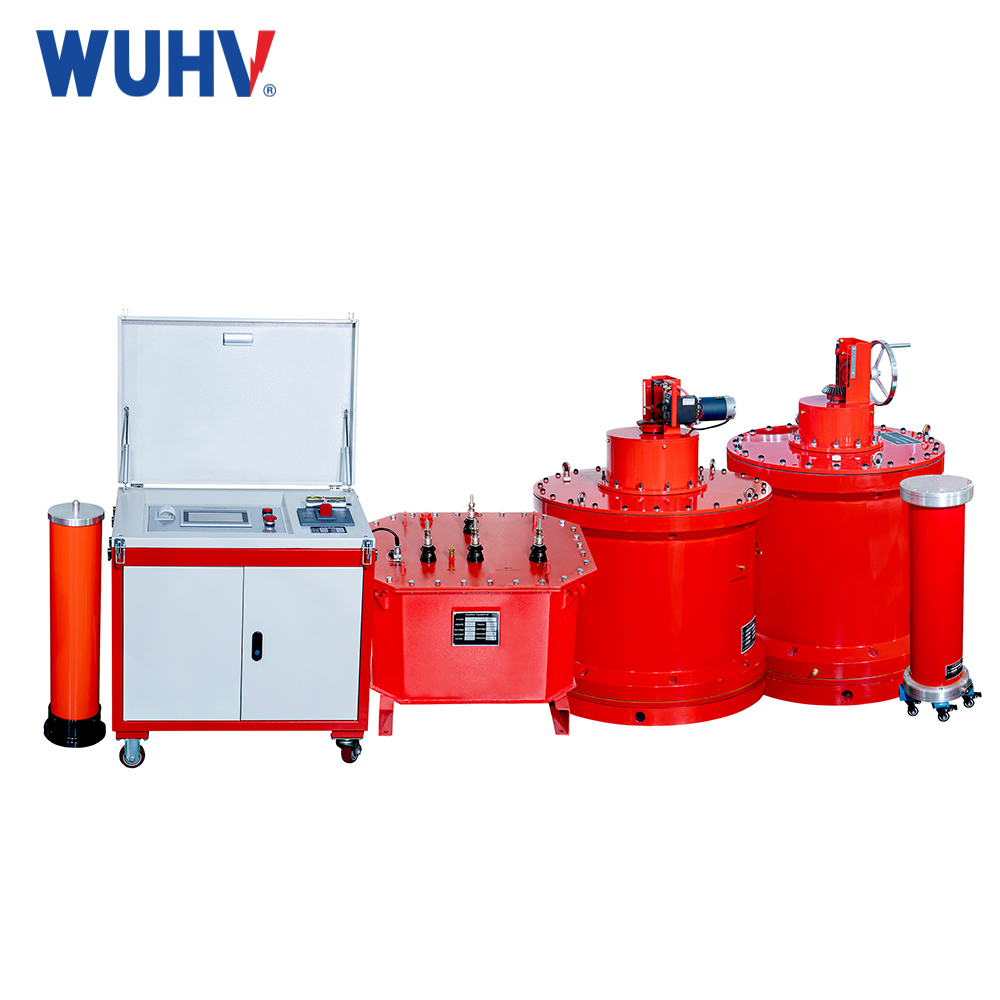
Asynchronous motor test bench and synchronous motor belong to AC motors, and according to the number of phases, there are single-phase asynchronous motors, three-phase asynchronous motors, single-phase synchronous motors, and three-phase synchronous motors. We will take the three-phase asynchronous motor test bench and three-phase synchronous motor as examples to explain the working principle of AC motors.
When three-phase asynchronous motors and three-phase synchronous motors are in operation, their three-phase stator windings are connected to a three-phase AC power supply, which provides three-phase AC current and generates a rotating magnetic field inside the motor. This magnetic field connects the stator winding and rotor winding, realizing the transfer and conversion of energy from the stator to the rotor. Therefore, the conversion of the rotating magnetic field and force of an AC motor is the key to its operation.
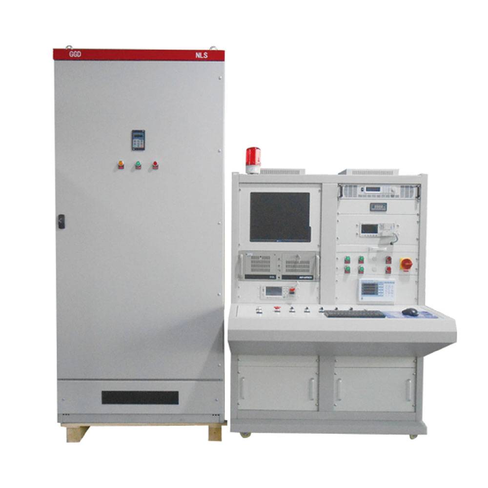
First, let's take a look at some basic knowledge about magnetic fields.
01 Basic knowledge about magnetic fields and forces
Right-hand spiral rule
Also known as Ampere's rule, it is a rule that represents the relationship between current and the direction of magnetic field induced by current. In short, it is used to determine the polarity of an energized coil. Ampere's rule in electrified straight wires (Ampere's rule one): Hold the electrified straight wire with your right hand and point your thumb in the direction of the current in the wire. Then, the four fingers point in the direction of the magnetic field around the electrified wire; Ampere's rule in an energized solenoid (Ampere's rule two): Hold the energized solenoid with your right hand and point your four fingers in the direction of the current, so that the end pointed by your thumb is the N pole of the energized solenoid.
Left-hand rule
The left-hand rule is used to determine the direction of force on an electrified wire in a magnetic field. Extend your left hand and let the magnetic field line penetrate your palm (with the palm aligned with the N pole and the back of your hand aligned with the S pole). Point your four fingers in the direction of the current, so that the direction of the thumb is the direction of the conductor's force.
right-hand rule
The right-hand rule is used to determine the direction of induced current generated in a conductor during the cutting of magnetic lines. Extend your right hand so that your thumb is perpendicular to the other four fingers and in the same plane as your palm. Place your right hand in a magnetic field and let the magnetic field lines penetrate vertically into your palm. If your thumb points in the direction of the conductor's movement, then the other four fingers point in the direction of the induced current.
02 Rotating magnetic field of AC motor
The stator winding of a three-phase AC motor is a three-phase symmetrical winding, consisting of three sets of windings with the same shape and number of turns, and whose axes are 120 ° apart in spatial position.
When three-phase AC current flows through the stator winding and ω t=0, iU is zero and there is no current; IV is a negative current flowing from U2 to U1; iW is a positive current flowing from W1 to W2; according to the right-hand screw rule, the direction of the composite magnetic field of the three-phase winding is determined as follows
In a magnetic field, the direction flowing towards the inside of the paper is defined as the positive direction, represented by ·, and the direction flowing towards the outside of the paper is defined as the negative direction, represented by ×.
When ω t=2 π/3, iU is a forward current flowing from U1 to U2; iV is zero and there is no current; IW is a negative current flowing from W2 to W1; the direction of the composite magnetic field of the three-phase winding is determined by the right-hand screw rule
When ω t=4 π/3, iU is a negative current flowing from U2 to U1; iV is a positive current flowing from V1 to V2; iW is zero and there is no current; Judging the direction of the synthesized magnetic field of the three-phase winding by the right-hand spiral rule
When ω t=2 π, iU is zero and there is no current; IV is a negative current flowing from V2 to V1; iW is a positive current flowing from W1 to W2; the direction of the composite magnetic field of the three-phase winding is determined by the right-hand screw rule
From the above analysis, it can be seen that the synthetic magnetic field rotates in space. When the current of the asynchronous motor test bench changes for one cycle, the two pole magnetic fields rotate in space for one cycle.
The above is the case of a pair of poles. Similarly, when the magnetic field is two pairs of poles, for every cycle of current change, the magnetic fields of the two pairs of poles rotate half a circle.
The rotational speed of the rotating magnetic field formed by the stator winding is called the synchronous speed n1, where p is the number of pole pairs of the magnetic field and f1 is the three-phase electrical frequency.