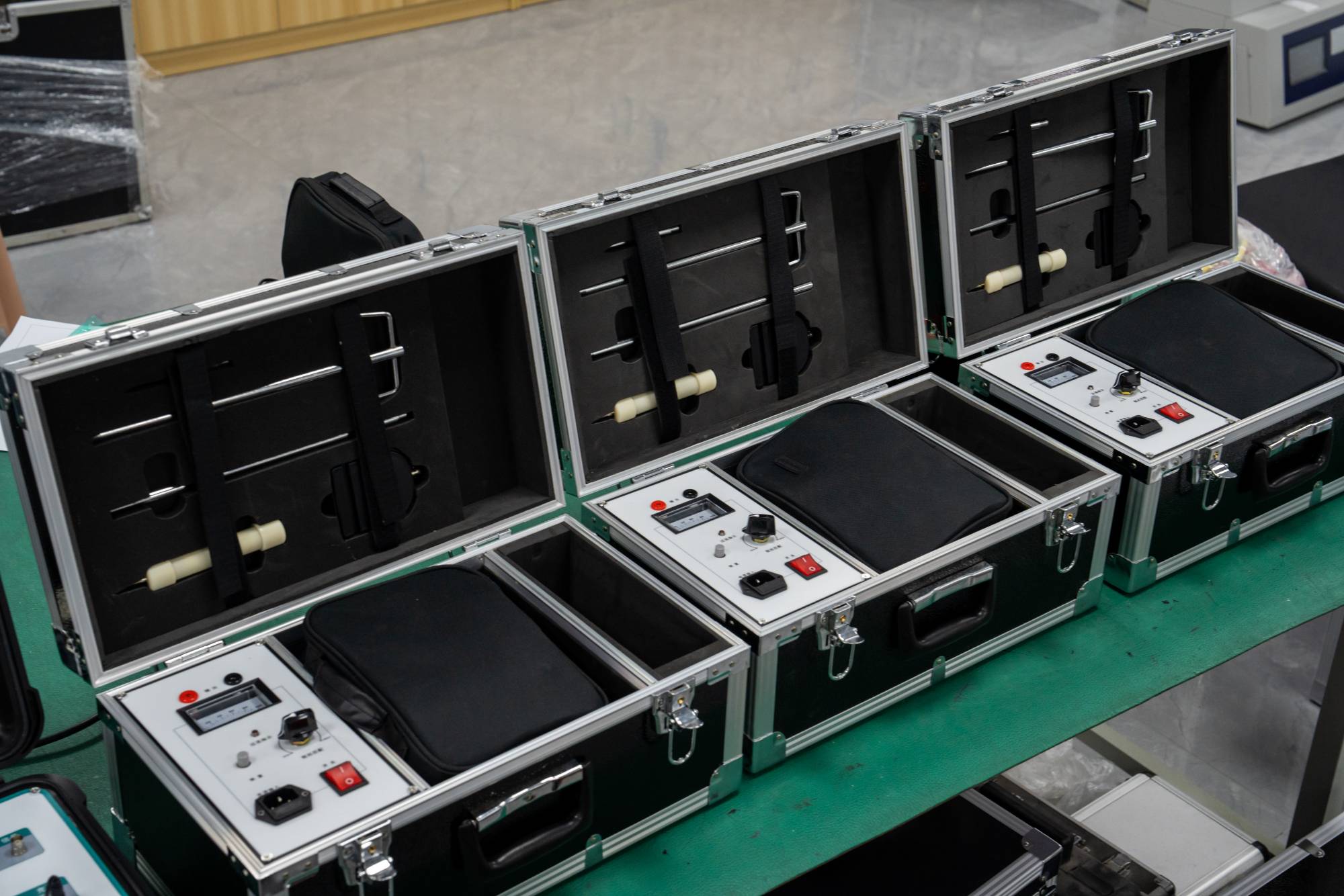
The cable fault tester under UHV power can help many power workers conduct various power tests more conveniently.
The power cable fault tester consists of three main parts: the power cable fault tester host, the cable fault locator, and the cable identifier. The host of the cable fault tester is used to measure the nature of cable faults, the total length and approximate location of the cable fault point at the testing end. The cable fault indication device determines the location of the cable fault point based on the approximate position of the cable fault tester host, in order to identify the cable fault point.
For buried cables with unknown directions, a path meter is used to determine the underground direction of the cable. The basic method for testing power cable faults is to apply high-voltage pulses to the faulty power cable, causing a fault at the fault point of the cable. At the same time as the cable breaks through the breakdown point, electromagnetic waves are generated and sound is produced simultaneously.
The working principle of the arc reflection method (secondary pulse method) in the positioning of the cable fault tester is to first apply a high voltage pulse with a certain voltage of, on the faulty cable at the cable testing end, so that the cable has a high resistance fault point. A breakdown arc occurs.
At the same time, low-voltage pulses for measurement are added to the testing end, and when the measurement pulse reaches the high resistance fault point of the cable, it encounters an arc and reflects on the surface of the arc. Due to arc discharge, high resistance faults become instantaneous short-circuit faults, and low-voltage measurement pulses undergo significant impedance characteristic changes. Therefore, the waveform of flashover measurement becomes a low-voltage pulse short-circuit waveform, making waveform recognition particularly simple and clear. This is what we call the 'secondary pulse method'.
The reflected waveform of the received low-voltage pulse is equivalent to the waveform of the iron core completely short circuited to ground. When the high voltage pulse is released and the low voltage pulse waveform obtained when the high voltage pulse is not released is superimposed, the two waveforms have a divergence point, which is the reflection waveform point of the fault point. This method combines low-voltage pulse and high-voltage flashover technology, making it easier for testers to determine the location of faults.
Compared with traditional testing methods, the advanced part of the secondary pulse method is to simplify the complex waveform in the impulse high-voltage flashover method into a simple low-voltage pulse short-circuit fault waveform. Therefore, explaining the extremely simple fault distance can accurately calibrate it.


